What is Rectifier?
Rectifier is the device which converts alternating current(AC) into direct current(DC). The alternating current periodically reverse its direction whereas the direct current does not periodically change its direction.
What is Half-Wave Rectifier?
How does Half-Wave Rectifier functions?

Circuit Diagram of Half-Wave Rectifier
The circuit diagram of Half wave rectifier is as shown below.

The voltage is applied at the primary side of the transformer. The low voltage is induced in the secondary of the transformer according to the turns ratio of the transformer. The voltage is reduced to get desired DC voltage.The simplified equivalent secondary circuit of the rectifier is as below.

During the positive half cycle of the AC waveform, the voltage at the anode of the diode is more than its cut-in voltage and diode becomes forward biased and starts conducting. Thus in the positive half cycle diode remains in the conducting state and currrent flows through the diode. The diode has very low forward resistance during its state of forward biasing and diode can be considered as short circuit, considering zero forward resistance.

The diode stops conducting when the AC waveform crosses the zero and goes towards the negative half cycle. During negative half cycle the diode is reversed biased and no current flow through the diode.During negative half cycle, the diode is open circuit and the rectifier equivalent circuit is as given below.
 During negative half cycle the reverse resistance of the diode is very high and it act as an open circuit and, the diode does not allow current to pass through it.
Half Wave Rectifier Formula
We will dicuss now the various formulas of half wave rectifier for assessing its performance.
Average value or DC value of Half Wave Rectifier
The average or effective DC output of half wave rectifier can be determined by taking the averge of the DC output voltage. The instaneous value of current at output of the rectifier is i=ImSinωt. The average load current across the load resistance is equal to:

RMS Value of Half Wave Rectifier
For a half-wave rectifier, the RMS load current (Irms) is equal to the average current (IDC) multiple by π/2. Hence the RMS value of the load current (Irms) for a half wave rectifier is:

Ripple Factor of Half Wave Rectifier
The ripple factor shows the effectiveness of rectification. The output of the rectified DC has AC component as well.The AC compnent is undesirable in the rectifed DC output and the AC component availble in the rectified DC is called ripple. It is practically impossible to eliminate the AC compont in the rectified DC output. However, the lesser ripples in the rectified waveform makes the output DC more smoother.
Ripple factor is defined as the ratio of AC component availbe in the rectifier output to averge value of DC output.

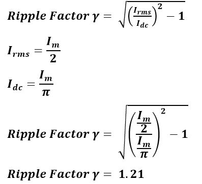
Ripple Factor of the Half Wave Rectifier can be expressed by following mathematical expression.

The ripple factor of the half wave rectifier is 1.21. The ripples factor can be lowered by installation of capacitor and inductor as a filter circuit.
Form Factor of Half Wave Rectifier
The ratio of RMS value and average value is known as form factor.

Efficiency of Half Wave Rectifier
The ratio between the output DC power and the input AC power is called rectifier efficiency. The formula for the efficiency is equal to:
 The efficiency of half wave rectifier is equal to 40.6%.
Peak Inverse Volatge of Half Wave Rectifier
The peak inverse voltage of the diode is the maximum voltage that a diode can withstand during reverse bias condition. If the voltage above peak inverse voltage(PIV) is applied, the diode is apt to fail.
Half Wave Diode Rectifier Applications
http://news.chivindo.com/300/single-phase-half-wave-rectifier--circuit-diagram-theory-amp-applications.html
Rectifier is the device which converts alternating current(AC) into direct current(DC). The alternating current periodically reverse its direction whereas the direct current does not periodically change its direction.
The half wave rectifier passes one half cycle of the alternating current and blocks the other half cycle.Thus in a one complete cycle of the AC waveform, half cycle is passed.In a half wave rectifier only one diode is used to convert AC into DC.
The main part of half wave rectifier is the diode.The diode conducts if the anode voltage is more than the cut-in voltage of the diode. The cut-in voltage of silicon and germanium diode is 0.7 and 0.3 Volts respectively. If the anode voltage is more than 0.7 volts, the diode starts conducting.In power electronics, silicon diodes are generally used because they have low value of forward resistance which make them suitable for delivering high forward current.

During one positive half cycle the diode conducts and passes the wave form for the period from o to π . The diode does not conduct for the period from π to 2π because the anode potential is less than the cut-in voltage of the diode. The output waveform of the diode is the DC voltage since it has positive pulses. The output DC waveform has more ripples and it is not smooth.
We can get negative DC voltage by making the diode conducting during negative half cycle of the AC waveform.
 The diode conducts during the negative half cycle of the AC waveform. During positive half cycle the diode is in reverse bias and no current flows through the diode.
We can get negative DC voltage by making the diode conducting during negative half cycle of the AC waveform.

The circuit diagram of Half wave rectifier is as shown below.

The half wave rectifier circuit consists of three main parts.
- Transformer
- Diode
- Resistive Load
The voltage is applied at the primary side of the transformer. The low voltage is induced in the secondary of the transformer according to the turns ratio of the transformer. The voltage is reduced to get desired DC voltage.The simplified equivalent secondary circuit of the rectifier is as below.

During the positive half cycle of the AC waveform, the voltage at the anode of the diode is more than its cut-in voltage and diode becomes forward biased and starts conducting. Thus in the positive half cycle diode remains in the conducting state and currrent flows through the diode. The diode has very low forward resistance during its state of forward biasing and diode can be considered as short circuit, considering zero forward resistance.

The diode stops conducting when the AC waveform crosses the zero and goes towards the negative half cycle. During negative half cycle the diode is reversed biased and no current flow through the diode.During negative half cycle, the diode is open circuit and the rectifier equivalent circuit is as given below.

Half Wave Rectifier Formula
We will dicuss now the various formulas of half wave rectifier for assessing its performance.
Average value or DC value of Half Wave Rectifier
The average or effective DC output of half wave rectifier can be determined by taking the averge of the DC output voltage. The instaneous value of current at output of the rectifier is i=ImSinωt. The average load current across the load resistance is equal to:

For a half-wave rectifier, the RMS load current (Irms) is equal to the average current (IDC) multiple by π/2. Hence the RMS value of the load current (Irms) for a half wave rectifier is:
Ripple Factor of Half Wave Rectifier
The ripple factor shows the effectiveness of rectification. The output of the rectified DC has AC component as well.The AC compnent is undesirable in the rectifed DC output and the AC component availble in the rectified DC is called ripple. It is practically impossible to eliminate the AC compont in the rectified DC output. However, the lesser ripples in the rectified waveform makes the output DC more smoother.
Ripple factor is defined as the ratio of AC component availbe in the rectifier output to averge value of DC output.
Ripple Factor of the Half Wave Rectifier can be expressed by following mathematical expression.
The ripple factor of the half wave rectifier is 1.21. The ripples factor can be lowered by installation of capacitor and inductor as a filter circuit.
Form Factor of Half Wave Rectifier
The ratio of RMS value and average value is known as form factor.
Efficiency of Half Wave Rectifier
The ratio between the output DC power and the input AC power is called rectifier efficiency. The formula for the efficiency is equal to:
Peak Inverse Volatge of Half Wave Rectifier
The peak inverse voltage of the diode is the maximum voltage that a diode can withstand during reverse bias condition. If the voltage above peak inverse voltage(PIV) is applied, the diode is apt to fail.
Half Wave Diode Rectifier Applications
- Power rectification: Half wave rectifier is used for rectification of AC to get DC Voltage.
- Signal demodulation: Through process of demodulation the signal is recovered. A half wave rectifier is widely used for demodulation of modulated signals.
- Signal peak detector: The simple half wave diode detector can be used as a peak detector, detecting the peak of an incoming waveform.
Advantages of Half Wave Rectifier
The half wave rectifier is very simple in construction.The half wave rectifier has very few numbers of components.
- Lower number of components
- Cheaper
Disvantages of Half Wave Rectifier
The disadvantages of the half wave rectifier are :
- Only half wave of AC is rectified and the other half- cycle is wasted. Therefore, its efficiency is very low(40%).
- The output DC volatge is low.
- The output DC contains more ripples and thus the output is not purely DC.
Solved Problems on Half wave Rectifier
The applied input power to a half wave rectifier is 200 watts.The DC power output of the rectifier is 80 Watts. What is the efficiency of the rectifier?
Rectification efficiency = Pout/Pin x 100
= 80/200 x100
= 40 %
An ac supply v= 60 Sin ωt is applied to half wave rectifier. The internal resistance of the diode(rf )is 20 Ω and load resistance is 600 Ω. Calculate - (1) Ac Power Input (2) DC power Output (3) Efficiency of rectification

An ac supply of 230 volts applied to step down transformer of 230/15 volts whose secondary is connected to the half wave rectifier.Find (1) The output DC Voltage (2) PIV of diode.

The applied input power to a half wave rectifier is 200 watts.The DC power output of the rectifier is 80 Watts. What is the efficiency of the rectifier?
Rectification efficiency = Pout/Pin x 100
= 80/200 x100
= 40 %
An ac supply v= 60 Sin ωt is applied to half wave rectifier. The internal resistance of the diode(rf )is 20 Ω and load resistance is 600 Ω. Calculate - (1) Ac Power Input (2) DC power Output (3) Efficiency of rectification
An ac supply of 230 volts applied to step down transformer of 230/15 volts whose secondary is connected to the half wave rectifier.Find (1) The output DC Voltage (2) PIV of diode.
Comments
Post a Comment