Current transformer are widely used for measuring the high current. The Current transformer steps down high value of current to low value which measuring instrument can read. If 2000 Amperes current to be read by a meter, it is not possible to read because a amall shunt resistance of high power rating in parallel to the galvanometer is required to be used. However, it is impractical to use a small value shunt resistance of high power rating to read high current directly by meter. That is why current transformer is used to lower the magnitude of the current so that measuring instrument and protective relay can read the current.
Construction of Current Transformer(CT)
The current transformer has two winding called primary and secondary. The primary winding has fewer number of turns and it is connected in series with primary circuit. The whole circuit current passes through the primary winding and it is desirable that the voltage drop across primary winding must be as low as possible. The current transformer has fewer turns of large cross section and, thus the voltage drop in the primary winding gets reduced up to a great extent.
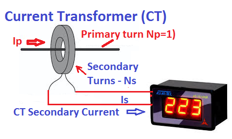
The seconadry winding has more number of turns compared to the primary winding and it is connected with ampere meter, energy meter, watt meter,transducer and protection relay. The secondary winding of the CT must be connected with low impedance meter to keep the magnetic flux in the core up to its rated flux capacity. The flux in the core above the rated capacity cause saturation of the magnetic core which leads to complete failure of current transformer. The CT secondary must not be left open because in this condition, the flux in the core increases manyfold and it cause CT core saturation.
Construction of Current Transformer(CT)
The current transformer has two winding called primary and secondary. The primary winding has fewer number of turns and it is connected in series with primary circuit. The whole circuit current passes through the primary winding and it is desirable that the voltage drop across primary winding must be as low as possible. The current transformer has fewer turns of large cross section and, thus the voltage drop in the primary winding gets reduced up to a great extent.
The seconadry winding has more number of turns compared to the primary winding and it is connected with ampere meter, energy meter, watt meter,transducer and protection relay. The secondary winding of the CT must be connected with low impedance meter to keep the magnetic flux in the core up to its rated flux capacity. The flux in the core above the rated capacity cause saturation of the magnetic core which leads to complete failure of current transformer. The CT secondary must not be left open because in this condition, the flux in the core increases manyfold and it cause CT core saturation.
Based on the construction, there are two types of current transformer- Live Tank CT and Dead Tank CT. In both types of CTs, the core and windings are enclosed in a porcelain structure and this structure is filled with mineral insulated oil which acts as cooling media, and it also provide required electrical insulation.
Symbol of Current Transformer(CT)
 The terminal P1 and P2 shows the primary winding of the CT and terminal S1 and S2 shows secondary winding of the CT. The CT ratio 2000/1 means the secondary current will be 1 ampere if primary current through the CT is 2000 amperes.
Equivalent Circuit of Current Transformer(CT)
The CT equivalent circuit is as given below.

The primary of CT has few turns and it has very less resistance. The primary winding resistance and reactance is denoted by Rp and Xp respectively. The secondary winding resistance and reactance is denoted by Rs and Xs respectively. The magnetisization components of the current transformer are Rc and Xm. Rc is responsile for the core loss component, and Xm is the magnetization reactance of CT. The other CT parameters are as given below.

Phasor Diagram of Current Transformer(CT)


The equivent circuit of the current transformer is similar to that of power tranformer and induction motor. From the phasor diagram the transformer ratio and phase angle can be calculated.
CT Transformation Ratio
CT transformation ratio is calculated as follows.For finding transformation ratio we need to calculate primary current Ip as per definition and then divide it by secondary current Is. Let us consider the part of phasor of our importance for calculating Ip as shown below.
 From the above phasor, the primary current Ip is phasor sum of nIs and I0. The CT primary current Ip can be calculated using vector addition formula.
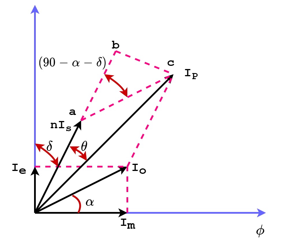

The magnetizing current Io is very small compared to the primary current Ip. Therfore, the above expression can be simplified as follows.

From above expression, it is clear that transformation ratio is not equal to turn ratio. The transformation ratio and turn ratio will be equal if α=0 and δ=0.This condition can be achieved if the core loss is equal to zero and the burden is purely resistive. This is an ideal condition, however this condition is practically impossible.
Phase Angle of Current Transformer
Phase angle of current transformer is defined as the angle between the primary current Ip and secondary current Is. In above phasor diagram, θ is the phase angle.

Ratio Error of Current Transformer
The CT ratio Error is defined as the per unit deviation in transformation ratio from its nominal ratio. Ratio error is expressed in percentage.

Since the burden of the CT is generally resistive, therfore the power factor of the burden is unity and hence δ=0

Phase Angle Error of Current Transformer
The phase angle between primary and secondary of the current transformer must be 180 degree.The primary and secondary current must be out of phase. The deviation in the phase angle of the primary and secondary current is called the phase angle error. The phase angle between primary and seconadry current of the CT is denoted by angle θ.
Since the burden of the CT is generally resistive therfore the power factor of the burden is unity and hence δ=0. The phase angle error of CT is given by following expression.

Since the burden of the CT is generally resistive therfore the power factor of the burden is unity and hence δ=0.
Comments
Post a Comment